Welding Lobe Diagram

Weld Lobe Diagrams For Z 0 Z 10 And Z 20 Specimens T M M D
Coated Steel Weldability Resistance Welding Lesson Objectives

Estimation Of Lobe Curve With Material Strength In Resistance

Comparisons Of Nugget Thickness Versus Welding Current In Welding
Uncoated Plain Carbon Steel Material Variables Uncoated Plain

Resistance Spot Welding
1 weld lob is to find the best or suitable welding condition for given combination of sheets.
Welding lobe diagram. This is a very important concept to eliminate all expulsion. In this study we obtained the welding force vs welding current lobe diagram for commonly used ga steel plate and found that the second order repression model of tensile shear strength was useful. A robust weld lobe diagram delimits a volume in 3d an area in 2d within which all values of force current and time have good probability of giving acceptable results. Welding lobe could be widened with the use of optimized welding parameters.
10 and han et al. A weld lobe diagram is a two dimension graphical representation of ranges of welding parameters for a specific material and its thickness to compare an. In this study trip800 steel was used for the experiments. The weld lobe in spot welding provides an indication of good quality joining and the tolerance of the weld schedule in production stage.
Weldability lobe diagram is one of the most powerful techniques that can be used to il lustrate the effects of welding current and time. Resistance spot welding of aluminum alloy sheet 5j32 using scr. The low limit of the range of the optimal welding condition was decided by the lower limit of the. A characteristic was compared and analyzed between the lobe diagram of scr type resistance spot welding and that of inverter type resistance spot welding of.
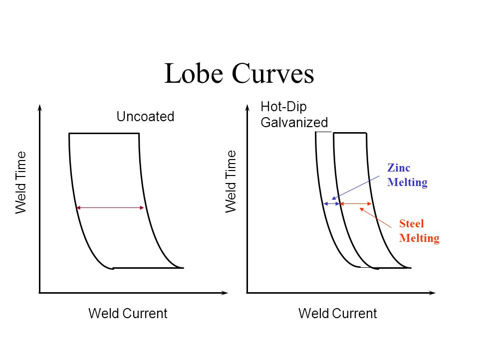
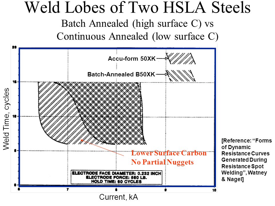
11 employed the lobe diagram to investigate the acceptable welding current and time for high strength steel. Welding aluminium sheet metal spot welding lobe diagram. Titanium coated electrodes can further increase the width of the welding lobe allowing an increased range of operating currents during welding. Under certain conditions a larger lobe can be achieved using 2 pulse weld current input over 1 pulse and 3 pulse inputs.
In this study trip800 steel was used for the experiments and welding times of 5 10 15 20 and 25 cycles were selected with welding currents ranging from 1 to 7 ka with an interval of 2 ka and from 7 to 10 ka with an interval of 1 ka. Resistance spot welding of aluminum alloy sheet 5j32 using scr type and inverter type power supplies d c. Standard procedures that can be followed to develop spot weld lobes are found in.

The Mimetic Diagram And Shape Of Nugget With Various Weld Current

Estimation Of Lobe Curve With Material Strength In Resistance

Pdf Optimization Of Resistance Welding By Using Electric Servo

Effect Of Welding Current On Nugget Diameter And Failure Mode In
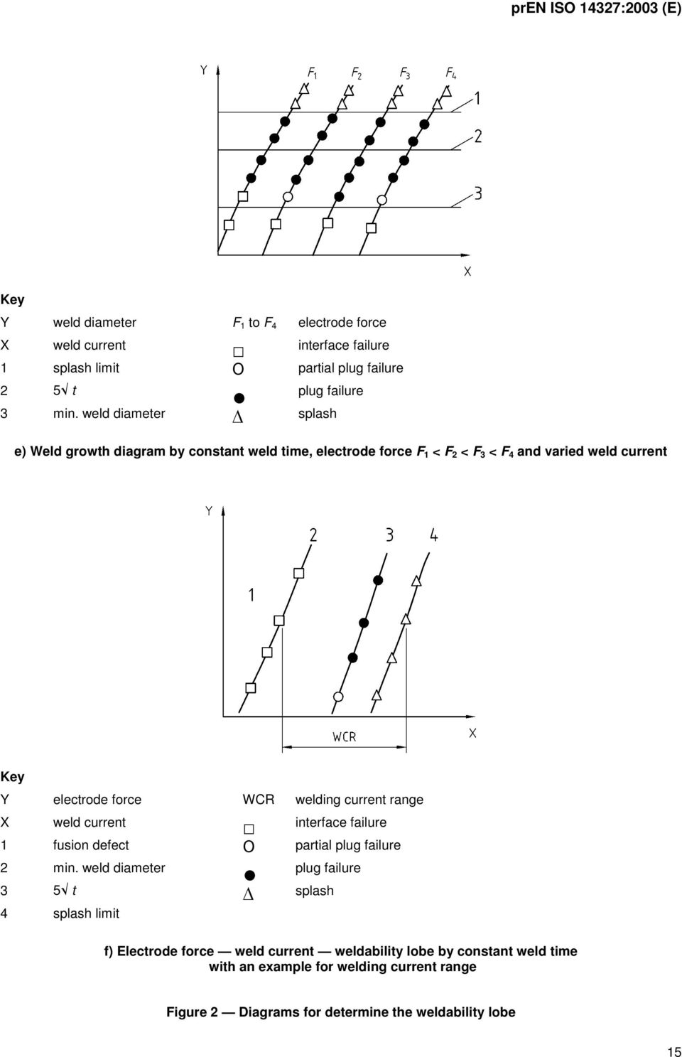
Final Draft Pren Iso Resistance Welding Procedures For Determining

Pdf Dissimilar Spot Welding Of Dqsk Dp600 Steels The Weld Nugget

Tecna 4621 Spot Welding Machine Download Scientific Diagram

Pdf Evaluation Of Weldability And Mechanical Properties In
